
Lawn Care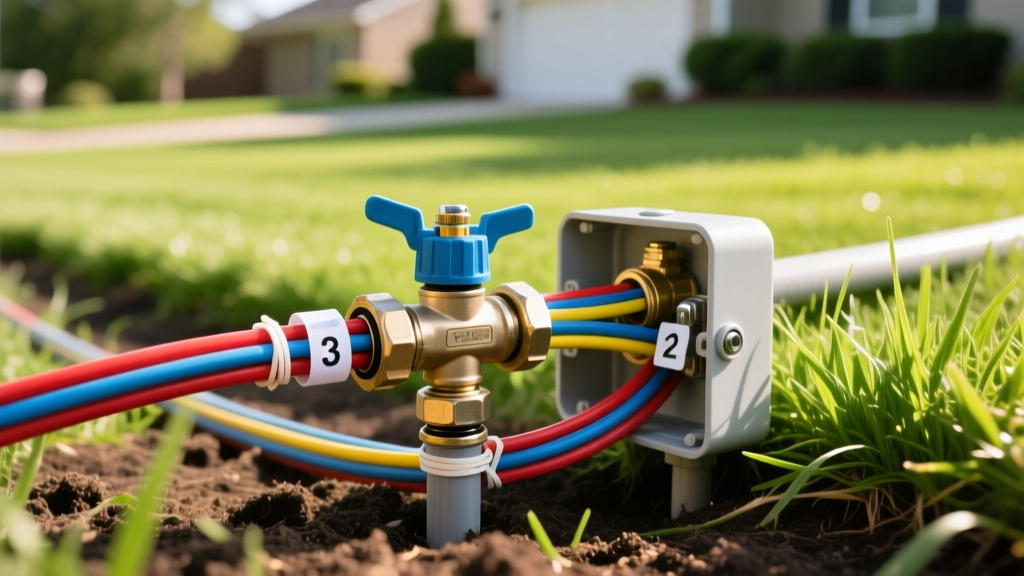
Irrigation Wiring Guide: Connect and Troubleshoot Sprinkler Valves
Understanding 24 VAC Irrigation Wiring Architecture
Irrigation wiring forms the nervous system of any automated lawn sprinkler setup. Unlike standard household electrical systems that operate on 120V or 240V line voltage, residential and light-commercial irrigation systems utilize low-voltage 24 VAC (Volts Alternating Current) supplied by a step-down transformer inside the controller. This low-voltage architecture powers the solenoid coils on each valve, creating the electromagnetic field required to open the diaphragm and release water.
A standard irrigation wiring circuit consists of a single common wire (universally coded white in multi-wire bundles) and individual hot wires (color-coded red, blue, green, yellow, etc.) for each zone. The common wire runs continuously from the controller to every valve manifold in the yard, daisy-chaining from one valve to the next. The hot wires run from individual controller terminals directly to their corresponding zone solenoids. Understanding this parallel circuit design is critical before attempting any repairs or expansions.
⚠️ Safety Warning: While 24 VAC is generally safe and won't cause lethal shock, the primary transformer inside the controller is connected to 120V line voltage. Always disconnect the main power breaker and unplug the controller backup battery before opening the controller panel or splicing wires near the source.
Wire Gauge Selection and Voltage Drop
Selecting the correct wire gauge is the most common point of failure in DIY irrigation wiring. Using wire that is too thin for the distance of the run results in voltage drop, causing the solenoid to chatter, fail to open, or burn out prematurely. Solenoids require a minimum of 19 VAC to actuate reliably. According to Texas A&M AgriLife Extension, maintaining adequate voltage at the furthest valve is essential for system longevity.
| Wire Gauge (AWG) | Max Recommended Distance | Primary Use Case | Cost per 250ft Spool |
|---|---|---|---|
| 18 AWG (Solid Copper) | Up to 800 feet | Standard residential zones (1-8 valves) | $35 - $45 |
| 14 AWG (Solid Copper) | 800 to 1,500 feet | Large estates, commercial, or master valve runs | $65 - $85 |
| 18 AWG (Stranded) | Not Recommended | Avoid for direct burial; prone to galvanic corrosion | N/A |
Always purchase UF-B (Underground Feeder) rated, direct-burial multi-wire cable with a durable PVC jacket. Avoid cheap, thin-jacketed imports that degrade in alkaline soils or when exposed to lawn fertilizer chemicals.
Step-by-Step: Wiring a Sprinkler Valve Solenoid
Proper physical connections prevent 90% of all irrigation wiring faults. The environment inside a valve box is wet, muddy, and full of microbes that accelerate copper oxidation.
- Strip the Jacket: Use a wire stripper to remove 2 inches of the outer PVC jacket from the multi-wire bundle. Separate the individual conductors.
- Strip the Conductors: Strip exactly 3/8 inch of insulation from the common wire and the specific zone hot wire. Do not twist the bare copper strands together. Twisting prevents the gel from fully encapsulating the wires inside the connector.
- Insert into Gel Cap: Push the bare wires straight into a grease-filled silicone connector (e.g., Toro EZ Connect or 3M Scotchlok UR2) until they hit the internal stop.
- Crimp and Seal: Using standard lineman pliers, squeeze the cap firmly until you hear or feel the internal brass U-tap bite through the wire insulation. The silicone gel will ooze out slightly, indicating a complete waterproof seal.
- Secure the Slack: Leave a 6-inch service loop of wire coiled inside the valve box. Do not pull the wire taut, as ground settling will snap the connection.
Advanced Troubleshooting: Finding Shorts, Opens, and Ground Faults
When a zone fails to activate from the controller but works manually via the bleed screw, the issue is electrical. According to diagnostic protocols outlined by the University of Florida IFAS Extension, a digital multimeter is the only reliable way to isolate irrigation wiring faults without unnecessary digging.
The Multimeter Diagnostic Matrix
Set your multimeter to the Ohms (Ω) setting, typically the 200Ω range. Disconnect both the common wire and the zone wire from the controller terminals to test the field wiring and solenoid independently.
| Multimeter Reading | Diagnostic Meaning | Required Action |
|---|---|---|
| 20 to 60 Ohms | Normal. Solenoid and wiring are intact. | Check controller output voltage (should be 24-28 VAC). |
| OL (Over Limit) or >10k Ω | Open Circuit. Wire is cut, or solenoid coil is burned out. | Test solenoid directly at the valve. If solenoid reads 20-60Ω, the buried wire is severed. |
| 0 to 5 Ohms | Short Circuit. Wires are touching, or solenoid is internally shorted. | Disconnect solenoid. If reading remains low, the hot and common wires are shorted underground. |
| Fluctuating / Unstable | Moisture intrusion or loose connection at a splice. | Locate valve box splices and replace standard wire nuts with gel caps. |
Testing for Ground Faults
A ground fault occurs when the insulation on a hot wire is nicked by a shovel or edger, allowing the 24 VAC current to leak into the wet soil. This causes the controller to blow its internal fuse or display an "ERR" code. To test for a ground fault, set your multimeter to Ohms. Place one probe on the zone wire at the controller and drive a metal screwdriver into the bare earth, placing the second probe on the screwdriver. The reading should be infinite (OL). If it reads a specific resistance, your wire is compromised and leaking current into the ground.
Tracing Buried Wire Breaks Without Destroying the Lawn
When a multimeter confirms an open circuit, you must locate the physical break. Digging up the entire wire run is inefficient and damages turf roots. Professional irrigation technicians use specialized wire and cable locators, such as the Klein Tools ET300 or the Fox Hound ($150–$250 retail).
These devices inject a radio frequency signal into the broken wire. The transmitter is connected to the zone wire and a ground rod at the controller. You then walk the yard with the receiver wand. The audio tone will be loud and steady as you follow the path, but it will abruptly drop to silence exactly at the point where the copper is severed. Mark the spot with landscaping paint and excavate only a 12-inch square to access the break.
Waterproofing Repairs: Gel Caps vs. Silicone Sealant
When splicing a repaired wire, never use standard indoor twist-on wire nuts wrapped in electrical tape. Electrical tape adhesive breaks down in soil moisture within 18 months, leading to copper oxidation and recurring faults.
Expert Rule of Thumb: If you are repairing irrigation wiring, the only acceptable field connectors are grease-filled silicone capsules (like the 3M Scotchlok DBR/Y-6 for 14 AWG or UR2 for 18 AWG) or liquid-filled heat shrink tubes. The initial cost of $1.00 per connector prevents $200 in future diagnostic labor.
For larger splices involving 14 AWG commercial wire, use a Resin-Filled Splice Kit (e.g., Toro 89-0100). These kits provide a hard plastic shell that snaps shut over the wire nut connection, which you then fill with a two-part liquid polyurethane resin. The resin cures into a solid, waterproof block that is completely impervious to standing water inside flooded valve boxes.
Controller Terminal Maintenance
Faults aren't always buried in the yard. Inspect the controller terminal strip annually. Over time, the small flathead screws securing the wires can loosen due to thermal expansion and contraction. If you notice the common wire (white) is loose or shows green copper oxide, trim the wire back to bare, shiny copper, and re-seat it firmly. A loose common wire will cause multiple, seemingly unrelated zones to fail simultaneously or activate erratically.