
Lawn Care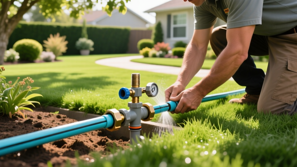
How to Plumb a Sprinkler System: Complete PVC & Poly Pipe Guide
The Anatomy of a Sprinkler Plumbing System
Learning how to plumb a sprinkler system requires more than just digging trenches and gluing pipes together. A properly designed irrigation plumbing network must manage static water pressure, minimize friction loss, and prevent water hammer. The physical plumbing consists of five distinct stages: the water source tap, the backflow preventer, the mainline, the valve manifold, and the zone lateral lines. Mistakes in pipe sizing or joint assembly at any of these stages will result in uneven water distribution, blown heads, or catastrophic pipe failures under pressure.
Before breaking ground, you must understand your baseline metrics. Measure your static water pressure using a pressure gauge attached to an outdoor hose bib (ideal residential pressure is 45 to 65 PSI). Next, determine your flow rate in gallons per minute (GPM) by timing how long it takes to fill a 5-gallon bucket. These two numbers dictate every pipe diameter and valve choice you will make.
Material Selection: PVC vs. Polyethylene Pipe
The two dominant materials for underground irrigation plumbing are Schedule 40 PVC and NSF-51 certified Polyethylene (poly) pipe. Your choice depends heavily on your regional climate and soil conditions.
| Feature | Schedule 40 PVC | 160 PSI Polyethylene |
|---|---|---|
| Best For | Warm climates, stable soils, high-pressure mainlines | Freeze-thaw climates, rocky/shift-prone soils |
| Connection Method | Solvent welding (primer + PVC cement) | Barbed insert fittings + stainless steel clamps |
| Cost (Approx.) | $4.00 - $6.00 per 10-foot stick (1-inch) | $45.00 - $65.00 per 100-foot roll (1-inch) |
| Freeze Tolerance | Low; will shatter if water freezes inside | High; expands slightly without rupturing |
| Friction Loss | Lower (smoother interior wall) | Slightly higher (corrugated interior texture) |
Step 1: Tapping the Source and Backflow Prevention
Your system must connect to the municipal water supply or a private well downstream of the main pressure tank. The most critical component in this stage is the backflow preventer, which stops contaminated irrigation water from siphoning back into your drinking water.
⚠️ Critical Code Warning: Never install a sprinkler system without a code-compliant backflow preventer. If you plan to inject fertilizers or pesticides through your irrigation system (fertigation), local plumbing codes universally mandate a Reduced Pressure Zone (RPZ) assembly, such as the Watts LF794 Lead-Free PVB/RPZ. For standard residential lawns without chemical injection, a Pressure Vacuum Breaker (PVB) like the Watts LF70 is typically sufficient. Always install the PVB at least 12 inches higher than the highest sprinkler head in your yard.
Connect the water source to the backflow device using copper, brass, or Schedule 80 PVC to handle the high-stress transition from the house plumbing. According to the EPA WaterSense program, ensuring proper backflow protection and leak-free source tapping is the foundation of an efficient, safe outdoor irrigation network.
Step 2: Trenching and Mainline Routing
The mainline carries pressurized water from the backflow preventer to the valve manifold. Because this pipe is under constant municipal pressure, it must be buried below the frost line or at a minimum depth of 12 inches in mild climates. Always call 811 before digging to have underground utilities marked.
When routing the mainline, avoid sharp 90-degree turns. Instead, use two 45-degree elbows to create a sweeping curve. This reduces turbulence and friction loss. For mainlines carrying up to 15 GPM, use 1-inch Schedule 40 PVC. If your flow rate exceeds 15 GPM, step up to 1.25-inch PVC to keep the water velocity below 5 feet per second, which is the industry threshold for preventing water hammer.
Step 3: Building the Valve Manifold
The manifold distributes water from the single mainline into individual zone lines. Pre-assembling the manifold above ground in a clean workspace prevents sloppy glue joints in muddy trenches.
- Cut and Prep: Cut your PVC pipe square using a ratcheting PVC cutter. Remove all burrs with a deburring tool, and chamfer the outside edge of the pipe by 1/16 inch using a file. This prevents the cement from being pushed into the fitting and creating a blockage.
- Prime: Apply a generous coat of clear PVC primer (e.g., Oatey Regular Body Clear Primer) to both the outside of the pipe and the inside of the fitting. The primer softens the plastic to create a chemical weld.
- Cement: Apply Oatey Medium-Body Clear PVC Cement over the primed areas. Do not use all-purpose cement; medium-body fills the microscopic gaps between the pipe and fitting.
- Join and Hold: Push the pipe into the fitting until it bottoms out, then give it a quarter-turn to distribute the cement. Hold the joint firmly for 15 to 30 seconds to prevent it from pushing back out due to air pressure trapped inside the fitting.
- Wire the Valves: Mount your valves (such as the Hunter PGV-100 1-inch globe valves) to the manifold. Connect the common wire and zone wires using grease-filled waterproof wire connectors to prevent corrosion.
Step 4: Zone Piping and Head Connections
Lateral zone lines operate under lower pressure and only pressurize when the valve opens. For these lines, 3/4-inch or 1-inch PVC is standard. However, the connection between the lateral pipe and the actual sprinkler head requires special consideration.
Avoid using rigid PVC risers to connect the pipe to the sprinkler head. If a vehicle or heavy mower runs over the head, the rigid pipe will crack. Instead, use a swing joint or funny pipe (1/2-inch flexible polyethylene). Funny pipe allows the sprinkler head to flex and absorb impact without transferring the stress to the main lateral line. Connect the funny pipe to the PVC lateral using a barbed x threaded fitting, and secure it with a single stainless-steel hose clamp tightened with a nut driver.
Troubleshooting Real-World Plumbing Failures
Failure: Water Hammer (Loud Banging in Pipes)
Cause: Fast-closing valves (especially diaphragm valves closing abruptly) create a shockwave when water velocity exceeds 5 ft/s in undersized pipes.
Fix: Install a water hammer arrestor near the quick-closing valve, or replace the mainline with a larger diameter pipe to reduce water velocity. Ensure your system's static pressure does not exceed 80 PSI; if it does, install a pressure regulator at the source.
Failure: Leaking Poly Pipe Insert Fittings
Cause: Poly pipe expands and contracts with temperature changes. A single hose clamp will eventually loosen as the plastic relaxes.
Fix: Always use two stainless-steel hose clamps per insert fitting. Offset the screws by 90 degrees to distribute the clamping force evenly. Tighten to 60 inch-pounds of torque.
Failure: Low Pressure at the Last Sprinkler Head
Cause: Excessive friction loss due to routing too many GPM through a 3/4-inch lateral line, or failing to account for elevation changes.
Fix: Refer to the Hunter Industries Design Guide friction loss charts. If you are pushing 12 GPM through a 3/4-inch pipe, friction loss will rob your system of pressure. Upgrade the first half of the lateral line to 1-inch PVC, then step down to 3/4-inch for the final heads.
Step 5: Pressure Testing Before Backfill
Never bury your pipes without testing them. A single failed glue joint will cost you hours of digging to locate and repair once covered with soil and sod.
Cap all open ends of your zone lines and mainline using threaded PVC caps wrapped in Teflon tape. Slowly open the main water valve to fill the system, allowing air to escape through a manually opened bleed screw on the manifold. Once the system is full and pressurized to your static line pressure, close the bleed screw. Let the system sit under full pressure for at least two hours. Walk the entire trench line looking for weeping joints, misting, or pooling water. Only after the system holds pressure flawlessly should you backfill the trench, ensuring you pack soil firmly beneath the pipes to prevent future settling and pipe sagging.