
Lawn Care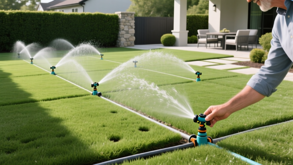
Designing a Sprinkler System Layout for Uniform Lawn Coverage
A poorly executed sprinkler system layout wastes up to 50% of applied water through runoff, wind drift, and uneven distribution, according to EPA WaterSense. Designing an efficient irrigation network is not about guessing where to drop sprinkler heads; it requires matching your property's hydraulic capacity to specific precipitation rates and topography. Whether you are retrofitting an existing system or planning a new install for a cool-season fescue lawn or a warm-season bermudagrass yard, this guide provides the exact engineering frameworks and product specifications needed to achieve uniform coverage.
Step 1: Site Audit and Hydraulic Capacity Mapping
Before drawing a single line on your layout plan, you must determine your available water pressure (PSI) and flow rate (GPM). Most municipal water supplies deliver between 40 and 65 PSI, but pressure drops significantly as water travels through pipes and fittings.
The Bucket Test for GPM
Locate the point of connection (POC)—usually the main water line after the meter but before any household pressure regulators. Use a 5-gallon bucket and a stopwatch. Time how many seconds it takes to fill the bucket. Divide 300 by the number of seconds to get your maximum available GPM. If it takes 20 seconds to fill a 5-gallon bucket, your available flow is 15 GPM (300 / 20 = 15).
Pro Tip: The 80% Safety Margin
Never design your zones to use 100% of your available GPM. Always multiply your maximum GPM by 0.80 to account for friction loss and simultaneous household water use. If your max is 15 GPM, design zones for a maximum of 12 GPM.
Never design your zones to use 100% of your available GPM. Always multiply your maximum GPM by 0.80 to account for friction loss and simultaneous household water use. If your max is 15 GPM, design zones for a maximum of 12 GPM.
Step 2: Selecting Sprinkler Heads by Precipitation Rate
The most catastrophic mistake in a sprinkler system layout is mixing head types with different precipitation rates on the same zone. According to the Rain Bird Design Guide, combining standard spray heads with rotors on a single valve guarantees that one area will drown while the other dries out.
| Head Type | Best Use Case | Precipitation Rate | Operating PSI | Estimated Cost (2026) |
|---|---|---|---|---|
| Standard Spray (e.g., Toro Precision) | Small, rectangular strips < 15 ft | 1.5 - 2.5 in/hr | 15 - 30 PSI | $3 - $6 per head |
| Gear-Drive Rotor (e.g., Rain Bird 5000 Plus) | Large open areas > 20 ft radius | 0.4 - 0.6 in/hr | 30 - 45 PSI | $15 - $22 per head |
| Rotary Nozzle (e.g., Hunter MP Rotator) | Medium areas, clay soils, slopes | 0.4 in/hr | 25 - 40 PSI | $8 - $12 per nozzle |
The Golden Rule of Zoning: Group heads by precipitation rate, not just by physical location. If a narrow 10-foot strip of grass sits between two large 30-foot rotor zones, that strip must be on its own dedicated spray-head zone, even if it requires running an extra wire and valve.
Step 3: The Head-to-Head Spacing Framework
Novice installers often space sprinkler heads based on their maximum diameter, assuming the water from two heads 30 feet apart will meet perfectly in the middle. This violates the physics of water distribution. Sprinkler heads distribute water in an inverse-square pattern: the highest volume of water lands immediately next to the head, and the volume tapers off significantly toward the edge of the throw.
How to Implement Head-to-Head Coverage
- Spacing equals Radius, not Diameter: If a rotor throws 30 feet, the next head must be placed exactly 30 feet away, not 60 feet.
- Corner and Perimeter Placement: Place heads in the corners of your lawn first, throwing water inward. Then, place heads along the perimeter, throwing inward and slightly overlapping.
- Interior Fill: Only after the perimeter is established should you place interior heads to ensure 100% head-to-head overlap across the entire turf area.
This 100% overlap ensures that the tapered edge of one head's spray pattern is compensated for by the heavy, concentrated center of the adjacent head's pattern.
Step 4: Pipe Sizing and Friction Loss Management
Your sprinkler system layout must account for friction loss—the reduction in water pressure caused by water rubbing against the interior walls of the PVC pipe. Undersized pipes will starve the furthest heads in a zone of pressure, resulting in misting and poor coverage.
Warning: Velocity Limits
Water velocity in PVC pipes should never exceed 5 feet per second (fps). Exceeding 5 fps causes water hammer, which can shatter PVC fittings and destroy solenoid valves over time.
Water velocity in PVC pipes should never exceed 5 feet per second (fps). Exceeding 5 fps causes water hammer, which can shatter PVC fittings and destroy solenoid valves over time.
Schedule 40 PVC Pipe Capacity Chart
| Pipe Size (Sch 40) | Max GPM (at 5 fps) | Friction Loss per 100 ft (at Max GPM) | Typical Application |
|---|---|---|---|
| 1/2 inch | 4 GPM | 4.5 PSI | Lateral lines to single spray heads |
| 3/4 inch | 10 GPM | 3.8 PSI | Small zone laterals (3-4 rotors) |
| 1 inch | 15 GPM | 3.2 PSI | Mainlines and large zone laterals |
| 1.25 inch | 22 GPM | 2.5 PSI | Primary mainlines from the POC |
For a standard residential layout, use 1-inch Schedule 40 PVC for the mainline (the pipe that is always pressurized and feeds the valves) and 3/4-inch or 1-inch for the lateral lines (the pipes that run from the valve to the individual sprinkler heads).
Common Sprinkler System Layout Mistakes
- Ignoring Microclimates: A zone that covers both deep shade under an oak tree and full-sun southern exposure will fail. The sun-baked area needs 30% more water than the shaded area. Split these into separate zones or use heads with built-in flow control (like the Rain Bird 1800-SAM-PRS) to manually throttle the shaded heads.
- Failing to Account for Wind Drift: If your lawn borders an open field or a coastline, avoid placing standard spray heads on the perimeter. Wind will carry the fine mist onto driveways and sidewalks. Use low-angle rotary nozzles (e.g., Hunter MP Rotator 90-210) which shoot heavier streams closer to the ground.
- Valve Placement in Low Spots: Always locate your anti-siphon or inline valve manifolds in well-drained areas. If a valve box sits in a topographical low point, it will flood during heavy rain, submerging the solenoid and causing electrical shorts in the irrigation controller.
Frequently Asked Questions
Can I use a hose-end sprinkler layout for an in-ground system?
No. Hose-end sprinklers are designed for high pressure and low flow, moving manually across a yard. In-ground systems require fixed, overlapping zones engineered around your specific static GPM and pipe friction loss.
How deep should I bury the PVC pipes in my layout?
Lateral lines should be buried 8 to 12 inches deep to protect them from aeration tines and shallow landscaping. Mainlines should be buried 12 to 18 inches deep. If you live in a region with a hard frost line, the mainline must be buried below the local frost depth or equipped with manual drain valves to prevent winter freeze damage.
Do I need a master valve on my layout?
Highly recommended. A master valve (installed immediately after the point of connection) keeps the entire mainline unpressurized when the system is not running. If a zone valve fails in the open position, the master valve will still shut off the water, preventing catastrophic flooding and massive water bills.